Drive QRS24 Installation
The Bont Rowing Drive QRS24 (Quick Release System) is designed to fit across all standard four-hole foot stretchers and can be installed using supplied hardware to both boat and shoes.
Note: FISA-approved heel ties and safety straps, included with all Bont Rowing shoes, must be adjusted appropriately and used at all times.
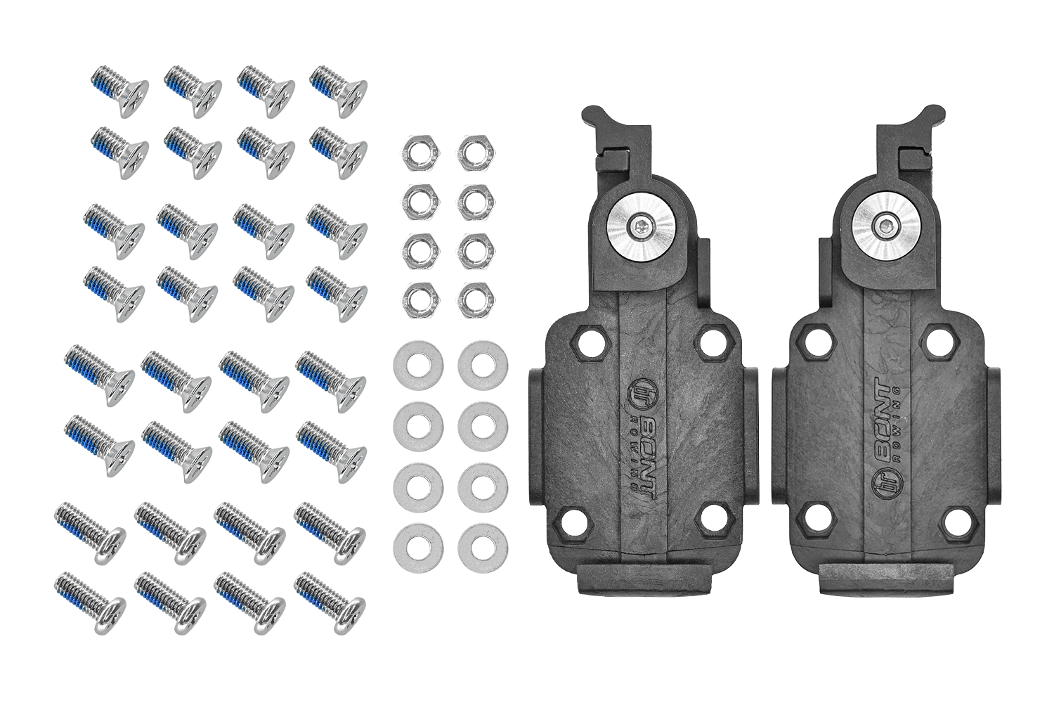
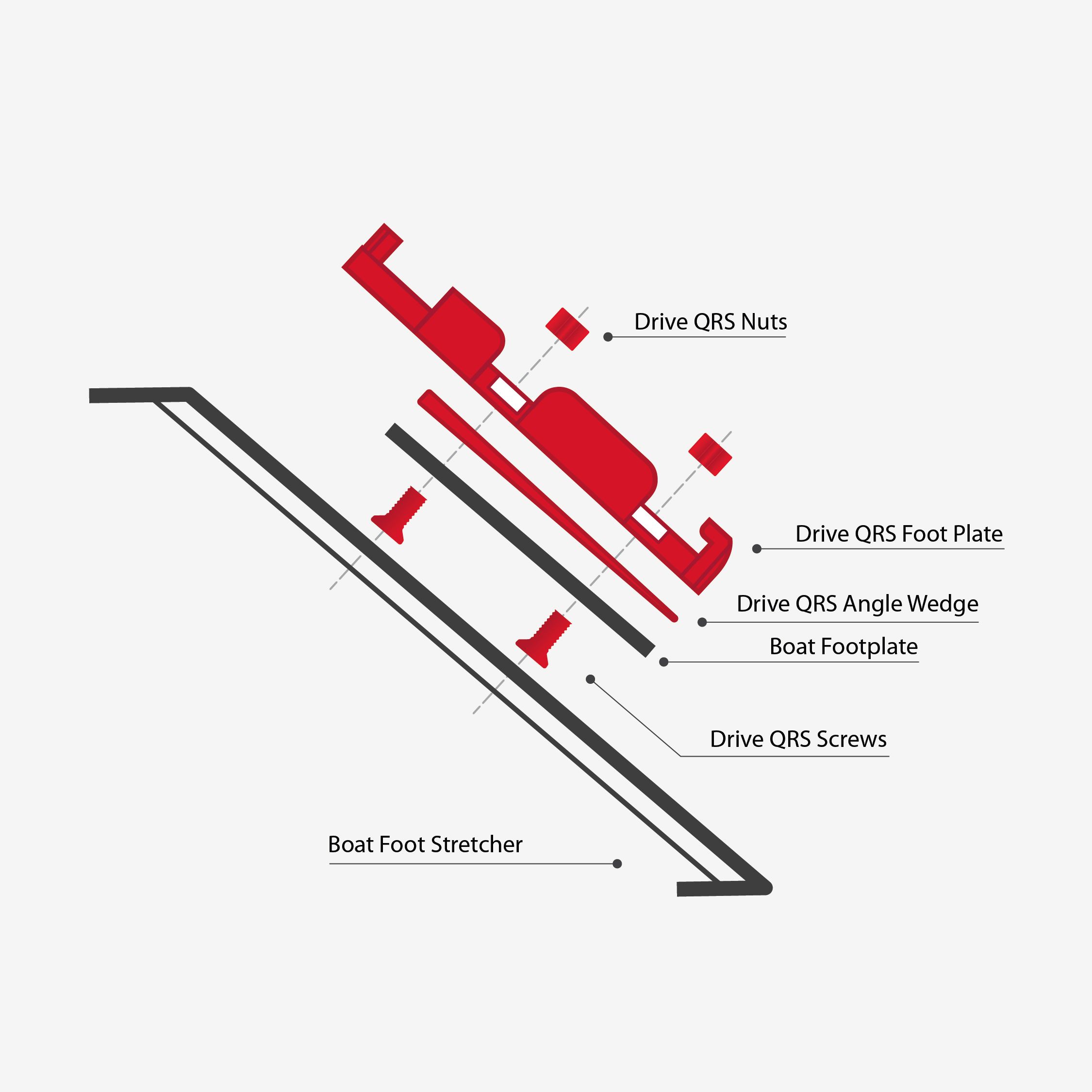
Drive QRS24 includes:
Foot Plate
- 2 x Drive QRS24 Foot Plates (left and right)
- 8 x M5, 10mm Countersunk screws
- 8 x M5, 11mm Countersunk screws
- 8 x M5, 12.5mm Countersunk screws
- 8 x M5, 14mm Flat Head Screws
- 8 x Washers (foot stretcher)
- 8 x M5 nuts (foot Stretcher)
Please note that you will need only 8 screws and 8 nuts to install the two footplates. The extra screws and washers provided are to ensure compatibility with the majority of footplate/stretchers available on the market.
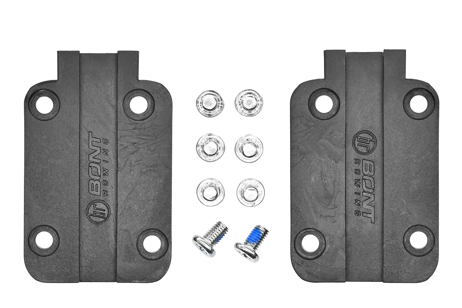
Shoe Plate
- 2 x Drive QRS24 Shoe Plates (left and right)
- 8 x M5, 10mm Flat Head screws.
QRS24+ (Plus) includes:
- 1 x Drive QRS24 complete kit (as listed above)
- 1 x Heel Set (contains Left and Right Heels)
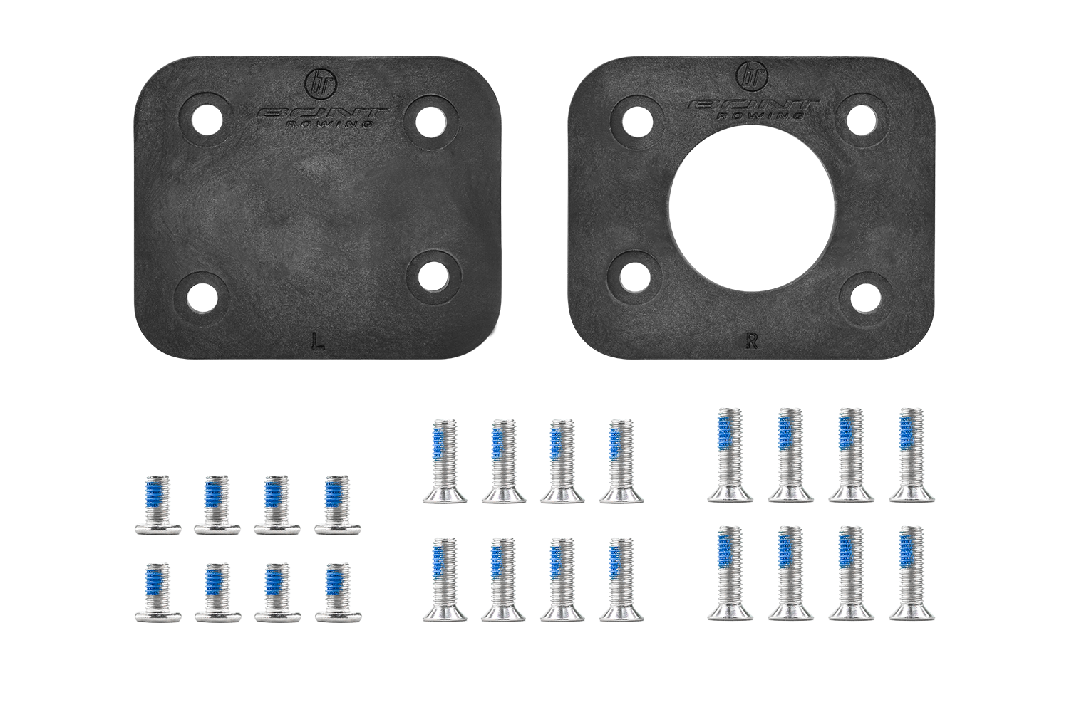
- 1 x Angle Wedge plates (contains Left and Right plates)
Sold Separately:
- Steering Plate.
Tools needed:
- Phillips Head Screwdriver
- Torque wrench rated to 5nM
Note: Foot stretcher and existing system (if applicable) will need to be removed prior to installation of the Drive QRS24.
Bont Rowing Drive QRS Drill Pattern
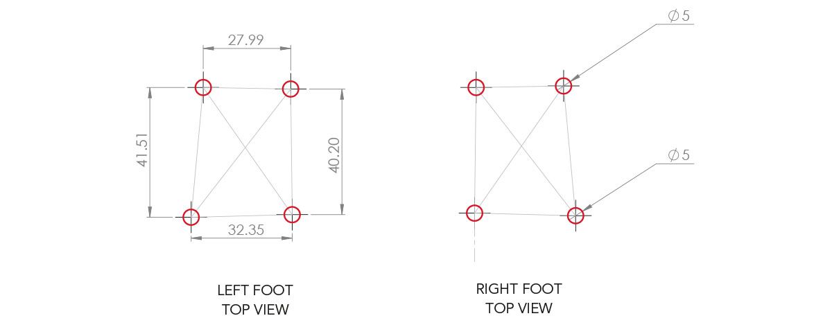
UNLESS OTHERWISE SPECIFIED:
- DIMENSIONS ARE IN MILLIMETERS
- SURFACE FINISH: Specified
- TOLERANCES: +/- 0.2mm
- DO NOT SCALE DRAWING
Notes:
- The highlighted 5mm holes are where the Bont Rowing Drive QRS Foot Plate is attached to the foot stretcher.
- The following drawings do not indicate or dictate splay or width, nor does it allow for fitting specifications within any one hull. These drawings are to be used with the accompanied DWG engineering file for use in detailing hole locations on a foot stretcher.
- Ensure to constrain relations between fastening points and rotate about the center point indicated for splay as each foot stretcher is individual.
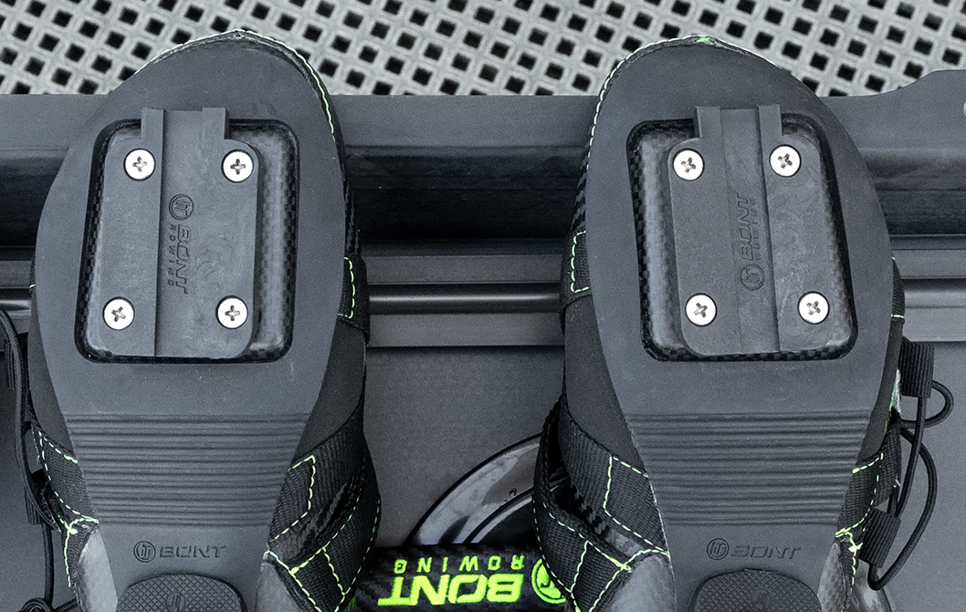
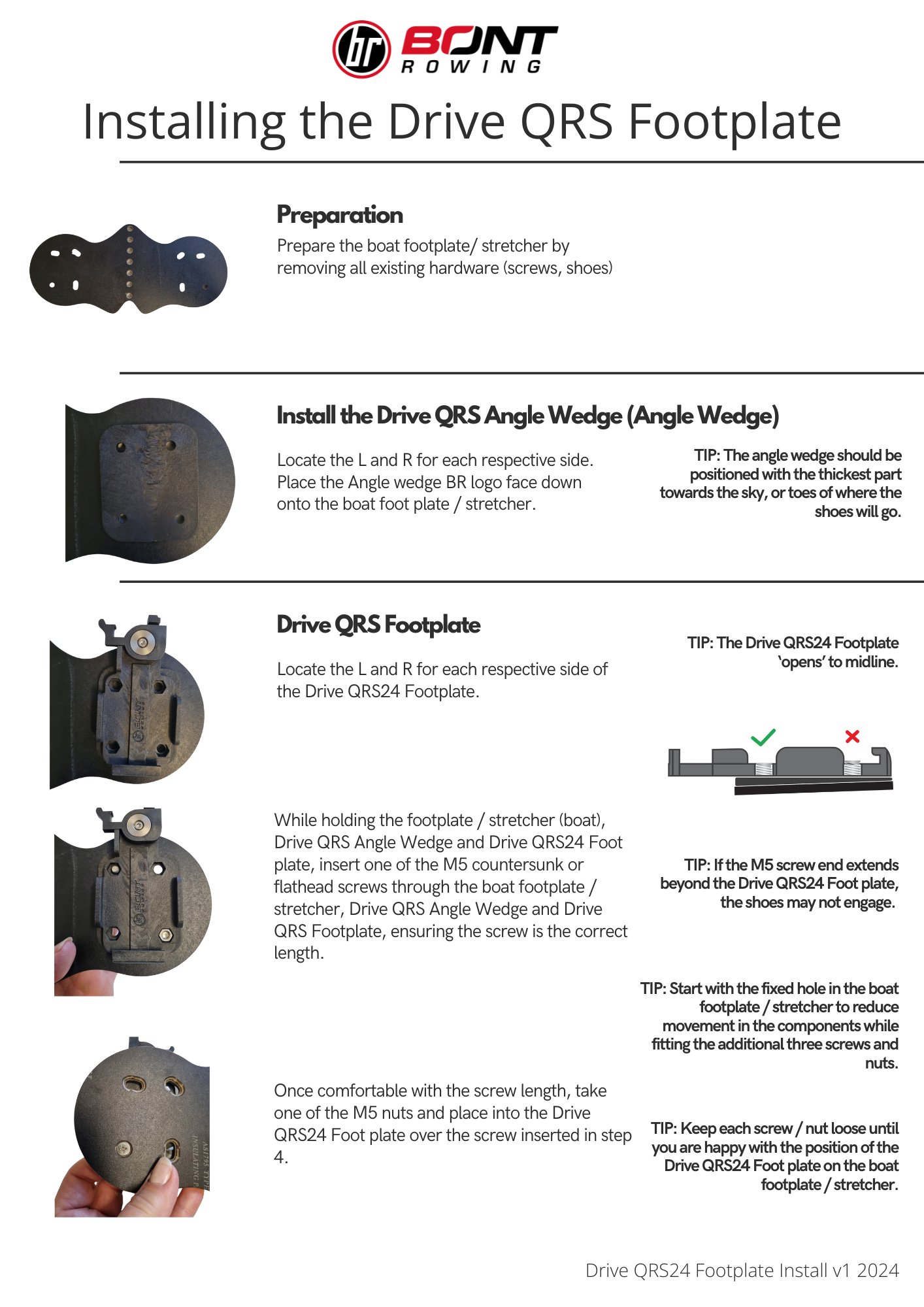
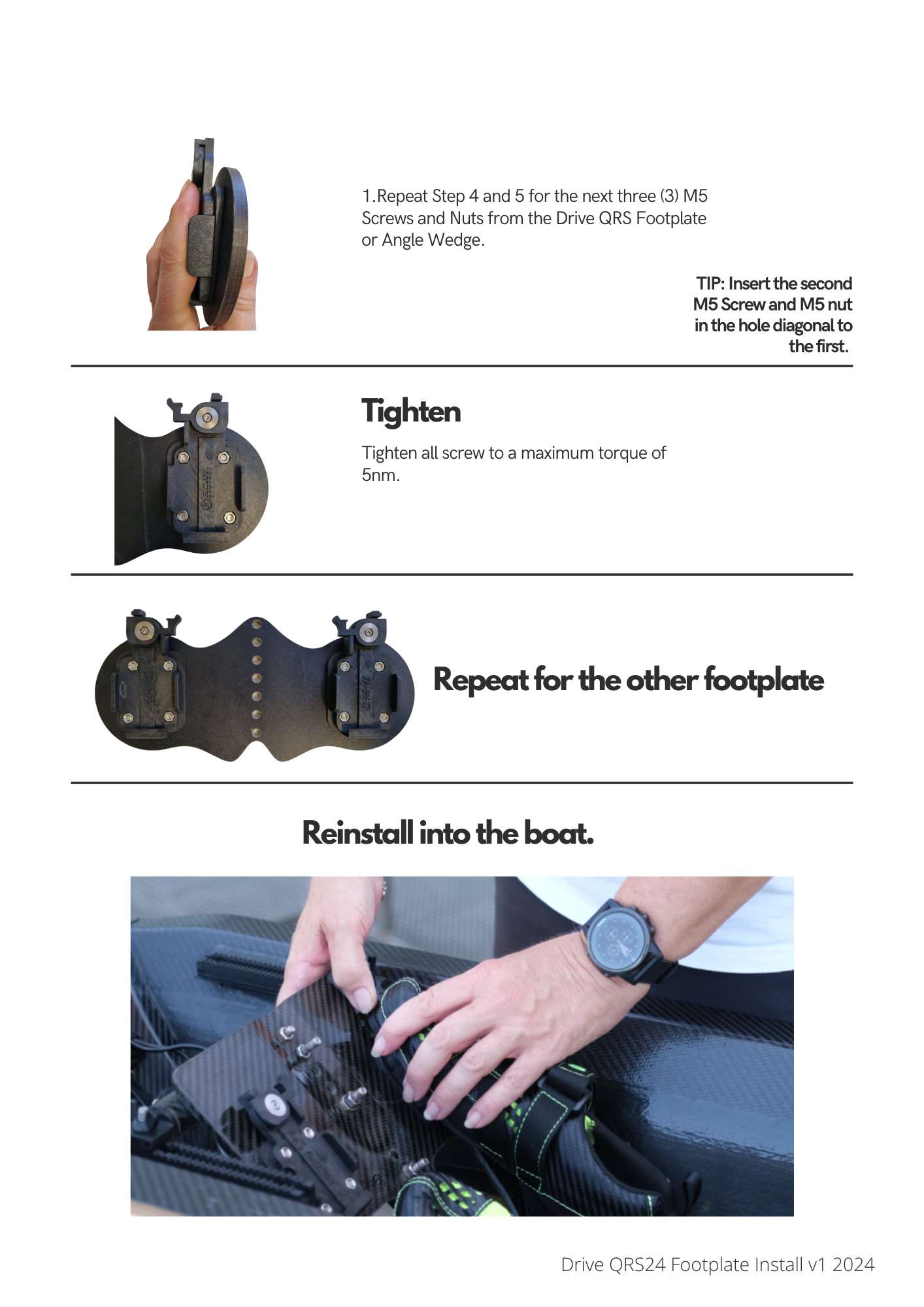
Instructions for Installing Drive QRS24 Shoe Plate
1. Place your shoes in an upturned position with the base of the shoe facing upwards (towards you).
2. Locate the L and R markings on each DQRS24 Shoe plate.
3. Take one shoe plate and place it onto the corresponding shoe.
4. Take one M5, 10mm Flat head screw and thread it into the top inner corner, keeping it loose. Take another M5, 10mm screw and thread it into the opposite corner.
5. Install the remaining screws, adjust the lateral adjustment to the best position then gently and evenly tighten. (Max 3nM).
6. Repeat for the other shoe.